
Home
General:
WARNING
FAQ
Links and reading
Animated project intro
Simple EEG instructions
Community Links
Main mailing list
Software-dev list
Wiki
SourceForge page
Hardware:
ModularEEG
Electrodes
Active
Passive
soundcardEEG
EEG Calibrator
EEG elsewhere
Olimex
Mindfield
Software
Neuroserver
BioEra
BrainBay
Brainathlon
ABI BCI
BWView
EEGMIR
ElectricGuru
BioExplorer
The text and graphics of this site are released under a Creative Commons license unless otherwise stated.
Simple EEG Assembly
This document assumes that you have done all the preparation in the Simple ModularEEG document, especially the testing.
You'll want to familiarise yourself with the following information:
| PCB |
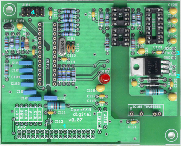
Picture key | Picture of item; The cyan-colored numbers in the photos mark the locations of the various connectors |
|---|---|---|
| The digital PCB |
|
 |
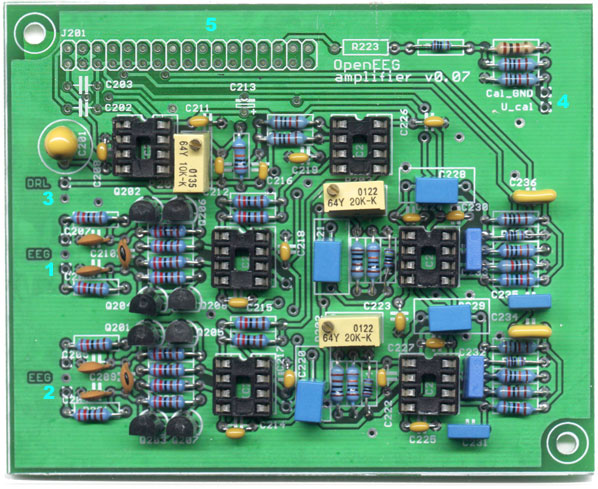
| The Analogue PCB |
|
 |
Basic Steps
Note that in the following instructions, rather than making the actual connections, you are plugging the appropriate pinhead connector to the PCB. You should have attached the pinhead connectors as per the instructions in the SimpleEEG Case and Cabling document.
If you have trouble following the pictures above, Andreas' lovely diagram may help a little.
- Filling the metal case (you need to do one of these for each Analogue board)
- If you are using multiple analogue boards, you will need to follow the (non-Simple) instructions at the Multichannel ModularEEG page.
- Mount the analogue PCB in the metal case
- Plug the electrodes into Analogue 1 and Analogue 2 (unnumbered J, but labelled "EEG ch1" and "EEG ch2")
- Plug the DRL into Analogue 3 (unnumbered J, but labelled "DRL")
- Ignore Analogue 4
- Plug one end of the PCB to PCB cable into Analogue 5 (J201)
- Drape the ends of the cables out of the box
- Close the box
- Filling the plastic case
- Mount the metal case(s) in the plastic case
- Mount the digital PCB in the plastic case
- Join the PCBs together with the PCB-to-PCB cable, from Analogue 5 in the metal box to Digital 1 (J102) on the digital board
- Plug the battery clip into Digital 2 (unnumbered J, but labelled to GND1 and PWR)
- Plug the 9-pin serial socket into Digital 3 (unnumbered J, but labelled RXD and TXD)
- Ignore Digital 4
- Close the case
- Plug in the external serial cable, the electrodes, and the DRL