From: Andreas Robinson (sleeper75se_at_yahoo.se)
Date: 2001-12-27 20:51:13
Hello folks,
here's my first and hopefully last design of the input
protection stage.
If you have the know-how, *please* take a look at it
and tell me what you think.
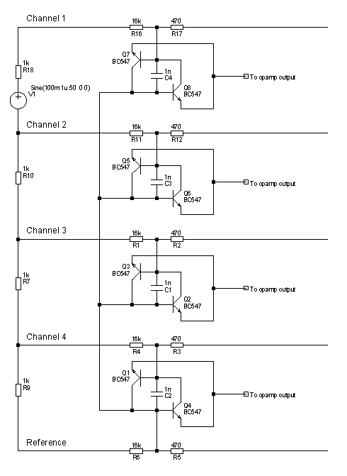
A short description is in order. I've attached a .gif
of the circuit, so go take a look at it.
The protection is based on Jim Meissners input
protection, the transistors are really used as diodes.
I'm exploiting the fact that below 0.7V they don't
conduct much current. Around 0.1V, where the input
stage will saturate anyway, the leakage is around 6pA.
I hope this is an accurate figure, and that it is low
enough.
Now, if anyone applies a couple of thousand volts to
the left side of the circuit, as when petting the cat
with a glass rod and then touching the electrodes with
it, the current generated is shunted through to the
opamp output, where perhaps a pair of diodes can pass
it through to the power rails. I'm not clear on what
to do there yet.
If two or more amplifiers fail so that one amplifier
input is connected to + and the other to -, the
transistors will again conduct the current, this time
from one power rail to the other, protecting the user.
The resistances to the left are calculated so that the
human is safe and the ones one the right so that the
transistors don't get fried.
Some specs:
For four channels, if three leads gets shorted to +6V
and two to -6V, which is the worst case, the current
through the user is 90uA with an electrode impedance
of 1K. The transistors get 9mA each. For FDA
approval, just change the 16K resistors to 33K.
Hopefully the noise levels are be ok with LT1012
amplifiers.
For two channels, you can use half the resistance for
the resistors on the left.
/Andreas
_____________________________________________________
Do You Yahoo!?
se.yahoo.com

This archive was generated by hypermail 2.1.4 : 2002-07-27 12:28:36 BST