From: Andreas Robinson (sleeper75se_at_yahoo.se)
Date: 2001-12-06 12:36:27
(This post is guaranteed fat-free, SNR=220dB)
Hello Joerg and Moritz, here are my comments on the
analog part of the modular eeg.
There are two issues I would like to bring to your
attention.
The first is input impedance, the other is VREF/2 that
is used as virtual ground.
-1-
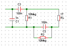
Look at the enclosed image of the input stage filter,
InputStageFilter.gif
To calculate the impedance that the electrodes 'sees',
simply treat all parts as resistors and use the rules
for parallel and serial connections:
Definition: A || B = AB / (A + B) ( = parallel
connection)
The network can then be described as
Z = ((C2 || R2 + RL) || R1 + C3) || C1
where
C1 = 10^9 / s (general formula: 1 /(s*C), where C =
capacitance)
C2 = 10^7 / s
C3 = 10^7 / s
R1 = 10^7
R2 = 10^7
RL = input impedance of the op-amp, in this case 10^12
s = 2*PI*f*i
i = square root of -1
f = frequency in Hz
This is way too much to compute by hand, but with a
HP48 calculator (or Matlab) it is very easy.
This table shows the results for a couple of
frequencies (in Hz).
Abs(Z) is the magnitude of the impedance, in megaohms.
Freq. | Abs(Z)
------+-------
0 infinity
0.01 157.9
0.5 10.4
1 10
2 9.9
10 8.4
20 6.2
30 4.7
40 3.7
50 3.0
60 2.6
As you can see, putting the filter in front of the
in-amp degrades its performance considerably.
My suggestion is that you move the filter to a point
behind the amplifier, just keep the circuitry needed
for protection - like the clamping diodes and a pair
of 100k resistors.
-2-
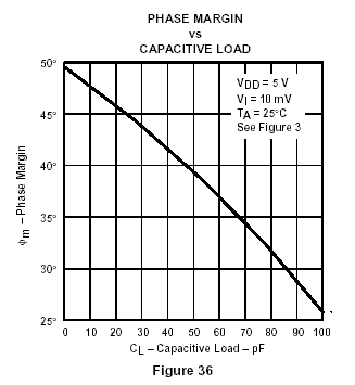
A picture says more than a thousand words, look at the
second image, CapacitiveLoading.gif taken from the
datasheet for TLC277.
The graph refers to Figure 3, which is basically a
buffer with a resistor and a capacitor hooked up in
parallel to the output and ground. The loading
resistor is 10k and the graph shows the phase margin
for different capacitances.
If the phase margin drops to zero degrees (or less),
the amplifier becomes unstable as the closed-loop
phase shift becomes -180 degrees and the negative
feedback becomes positive feedback - you get an
oscillator.
Extrapolating from the graph, it is likely that the
maximum stable load is about 200pF. Looking at the
schematics, there's 47uF sitting there (C31). A bit
over the limit don't you think?! :-)
Solution:
* dual supplies
or
* virtual ground (TLE2425, max 10mA, unsure how noisy
it is. Perhaps it is unsuitable)
or
* virtual ground for the filters and the old solution
(without the caps) for the instrumentation amplifier.
or
...
I'm sure the list can be made longer with som
net-surfing. I must admit I'm more used to using dual
supplies with bipolar designs.
/Andreas
_____________________________________________________
Nokia 5510, galet utseende, grymt ljud.
Gå till http://se.promotions.yahoo.com/nokia/ , upptäck
den och vinn den! Sista tävlingsdagen är 16 december 2001.


This archive was generated by hypermail 2.1.4 : 2002-07-27 12:28:33 BST